
Theory
When you take your measurements for this experiment, you will find the response of your diode for both the forward and the reverse bias modes of operation. If you took your data from both modes of operation and plotted it on a linear scale it would look similar to Figure below
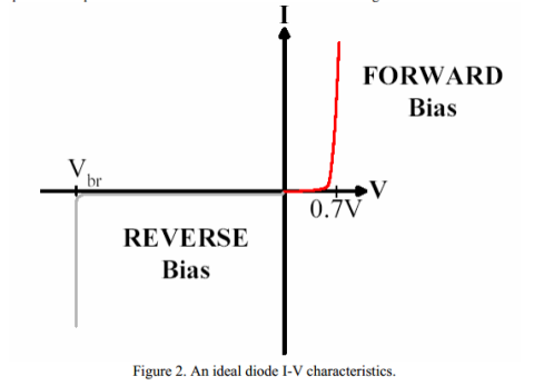
The Ideal diode equations is a fairly good approximation for the voltage ranges
Vb<Vappl< 0 V and a few kT/q V <Vappl< 0.7 V. Vappl is the voltage applied to the depletion region of the diode while Vbris the point at which a diode breaks down and conducts current in reverse bias. This equation is not valid from zero to approximately 0.05 V and less than Vbr. The Ideal Diode
Equation is,
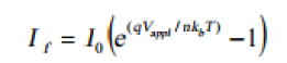
where the variable I0 in (1) is called the Reverse Saturation Current and is defined as,
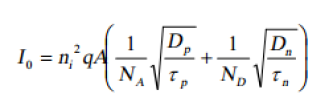
where Dp and Dn are the diffusion constants, τp and τn are the minority carrier lifetimes, and A is the cross sectional area of the junction area. The variable n is called the ideality factor. The ideality factor changes depending on the mechanism causing current flow in your semiconductor. One way of determining n is the following equation
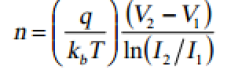
Where both (I1,V1) and (I2,V2) are points taken within the region where a particular current mechanism dominates. The chosen points should be taken a considerable distance away from each other on the voltage scale. (I1,V1) is identified as the lower voltage point and (I2,V2) is identified as the higher voltage point. We will address more about the ideality factor later, as we modify the ideal diode equation.


